| | Flat Tape System | Solid Circular System | Cable and Wire System | Accessories | |
|
|
How to apply structural lightning protection |
|
 | |||||||||||||||||||||||
Click on a link (on the right) for details. |
| ||||||||||||||||||||||
|
The first choice faced by the designer of a structural lightning protection system is the type of conductor system to be used.
Down conductor network The down conductor system is the means of carrying the current of a lightning strike safely to the earth termination network. | 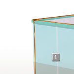 | ||||||||||||||||||||||
|
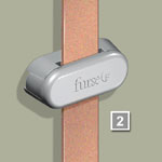
Select the correct system of fixings for each part of the conductor system. Fixings are available for a wide range of modern construction materials, eg brick, stone, plastic and metal.
|  | ||||||||||||||||||||||
Air termination network The air termination network is the point of connection for a lightning strike. It typically consists of a meshed conductor arrangement covering the roof of the structure. Use air terminals in the form of vertical air rods for the protection of prominent roof top features or equipment. Use strike pads to expose concealed conductors.
|  | ||||||||||||||||||||||
|
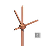
Choose the correct air terminal base. This will ensure that the
vertical air rods are both solidly fixed to the fabric of the structure
and have a low resistance connection to the conductor network. | 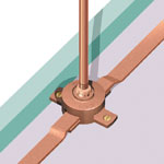 | ||||||||||||||||||||||
|
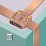
Select a component for the interconnection of multiple conductors or for changes of direction. Jointing clamps will ensure a low resistance, corrosion resistant connection.
| 
| ||||||||||||||||||||||
|
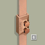
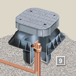
In order to allow periodic disconnection and testing of the earth termination network, select a test clamp to be placed within the run of each down conductor.
| 
| ||||||||||||||||||||||
|
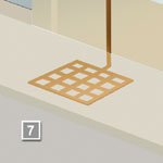
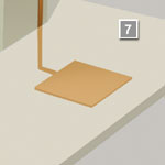
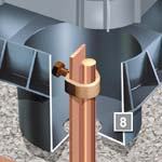
The means of dissipating the current to the general mass of earth. Earth electrodes Choose an earth electrode to suit the ground conditions in the locality of the structure. Electrodes are available in the form of rods and plates (lattice or solid).
|  
| ||||||||||||||||||||||
|
Select a high copper content alloy earth rod clamp for the connection of the earthing conductor to the earth rod. In this below ground application, the clamp must ensure a good electrical contact and resist corrosion throughout the lifetime of the installation.
| 
| ||||||||||||||||||||||
|
In order to allow periodic disconnection and testing of the earth termination network, select a test clamp to be placed within the run of each down conductor.
| 
| ||||||||||||||||||||||
|
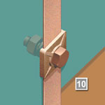
Bonding is the most commonly employed method of avoiding the damaging effects of side flashing. All continuous metalwork should be considered for bonding. All metallic services, eg cable armoring, gas, water or steam piping, entering the building should also be bonded as directly as possible to the earth termination network. Bonds to metalwork Select the correct type of metalwork bond for the application, i.e. a flat column face, a circular rainwater pipe or a ribbed reinforcing bar.
| 
| ||||||||||||||||||||||
| | Flat Tape System | Solid Circular System | Cable and Wire System Accessories | |