| esp product range | questions & answers |

Electronic Systems Protection furse

ESP PCB/06D, ESP PCB/15D, ESP PCB/30D, ESP PCB/50D & ESP PCB/TN PCB mount for data, signal and telephone lines

Suitable for "through hole" mounting directly onto the PCB of data communications, signal or telephone equipment.
Available for working voltages of up to 6, 15, 30 and 50 volts and telephone systems with a maximum working or ringing voltage of 190 volts.

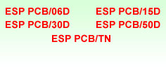
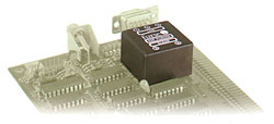
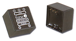
For wire-in, twisted pair signalling applications, see the ESP **D range. For systems requiring a PCB mounted protector with a very low resistance , higher current or higher bandwidth, see the ESP PCB/**E range.

Application

Use within OEM data communications, signal and telephone systems , where transient overvoltage protection needs to be integral to the unit.

Features and benefits

Suitable for wave soldering.

Low let-through voltage between all lines.

Provides repeated protection in lightning intense environments.

Low in-line resistance minimises unnecessary reductions in signal strength.

ESP PCB/**D
ESP PCB/**D

Two pin clean end and three pin line end to ensure correct insertion.

Simple earthing via central pin on line side.

ABS housing.

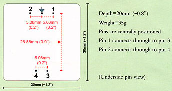
Installation

Connect in series, soldering pins direct onto PCB. Tracks to line and earth pins should be as wide as practical.

Electrical specification

ESP PCB/06D
ESP PCB/15D
ESP PCB/30D
ESP PCB/50D
ESP PCB/TN
Nominal voltage¹
16V
15V
30V
50V
*
Max working voltage²
7.79V
19V
37.1V
58V
190V
Current rating (signal)
300mA
300mA
300mA
300mA
300mA
In-line resistance
(per line ± 10%)
9,4 ohms
9,4 ohms
9,4 ohms
9,4 ohms
4.4 ohms
-3dB 50 ohm system
800kHz
2.5MHz
4MHz
6MHz
>50MHz

1 Nominal voltage (DC or AC peak) measured at <5µA (ESP PCB/15D, ESP PCB/30D, ESP PCB/50D) and <200µA (ESP PCB/06D).
2 Maximum working voltage (DC or AC peak) measured at <1mA leakage (ESP PCB/15D, ESP PCB/30D, ESP PCB/50D) and <10mA (ESP PCB/06D) and <95µA (ESP PCB/TN).
* Post transient recovery voltage >80V.

Transient specification

ESP PCB/06D
ESP PCB/15D
ESP PCB/30D
ESP PCB/50D
ESP PCB/TN
Let-through voltage (all conductors)¹
5kV, 10/700µs test to:
BS 6651:1999 Appendix C, Cat C-High
ITU (formerly CCITT) IX K17
10.5V
23.8V
43.4V
74.9V
200V
Maximum surge current
-per signal wire
-per pair
10kA
20kA
10kA
20kA
10kA
20kA
10kA
20kA
10kA
20kA

1 The maximum transient voltage let-through the protector throughout the test (+/-10%), line to line & line to earth. Response time <10ns.
2 Tested with 8/20µs waveshape to ITU (formely CCITT), BS 6651:1999 Appendix C. PCB tracking and connectors external to the protector may limit its capability.

Mechanical specification

ESP PCB/06D
ESP PCB/15D
ESP PCB/30D
ESP PCB/50D
ESP PCB/TN
Temperature range
-25°C to +70°C
-25°C to +70°C
-25°C to +70°C
-25°C to +70°C
-25°C to +70°C
Connection type
0.64mm (0.025") square PCB pins, 1.2mm diameter PCB holes recommended
Dimensions
Mechanical specification

PDF

ESP PCB Brochure