|
| esp product range | questions & answers | |
|
|
|
|

|

|
|
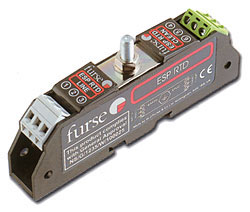
For For two wire or 4-wire RTD applications, use one or two ESP 06D protectors respectively. For three wire RTD applications where multiple RTDs are being protected see the ESP RTDQ. Application Use on three wires to protect monitoring equipment in RTD systems. Features and benefits |
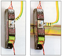
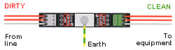
Installation Connect in series with the signal line either near where it enters or leaves the building or close to the equipment being protected (eg within its control panel). Either way, it must be very close to the systems earth star point. The screen connection should be made via the earth stud. Install protectors either within an existing cabinet/cubicle or in a separate enclosure. Suitable Accessories Simultaneously mount and earth up to 4 of these protectors on a CME 4, up to 8 on a CME 8, up to 16 on a CME 16 or up to 32 on a CME 32. Details of the Combined Mounting and earthing kits can be found here. Enclosures suitable for up to two (WBX 2/G) or three (WBX 3/G) protectors, or a CME 4 and its associated protectors (WBX 4), CME 8 and protectors (WBX 8) or two CME 16 kits and protectors (WBX 16/2/G) can be found here.
|
||
Electrical Specification |
| |
ESP RTD |
| Nominal voltage (note 1) |
6V |
| Maximum working voltage (note 2) |
7.79V |
| Current rating (signal) | 200mA |
| In-line resistance (per line +/-10%) | 10ohms |
| Bandwidth (-3dB 50ohm system) | 800kHz |
| 1 Nominal voltage (DC or AC peak) measured at <200ÁA 2 Maximum working voltage (DC or AC peak) measured at <10mA |
Transient Specification |
| |
ESP RTD |
| Let-through voltage - all conductors (note 1) 5kV, 10/700Ás test to: BS 6651:1999 Appendix C, Cat C-High ITU (formely CCITT) IX K17 |
10.5V |
| Maximum surge current (note 2) per signal wire per pair |
10kA 20kA |
| 1 The maximum transient voltage let-through the protector
throughout the test (+/-10%) line to line and line to earth. Response
time <10ns. 2 Tested with 8/20Ás waveshape to ITU (formely CCITT), BS 6651:1999 Appendix C. |
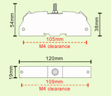
Mechanical Specification |
| |
ESP RTD | ||
| Temperature range | -25░C to +70░C | ||
| Connection type | Screw terminal | ||
| Earth connection | M6 stud | ||
| Weight unit packaged (per 10) |
0.08kg 0.85kg |
||
|
|||