Home › Lightning & Surges Protection › Electronic Systems Protection |
|
Protectors For Rail Applications |
|
To prevent transient overvoltage damage to Solid State Interlocking (SSI) systems, protectors should be fitted in trackside cabinets and equipment rooms, on both the data link and the mains power lines. Features and benefits
|
Network Rail Certification All the products on this page have Network Rail Certificates of Acceptance, allowing them to be used on Network Rail infrastructure.
Installation
Connect in series with the datalink either near where it enters the trackside location cabinet or the equipment room.
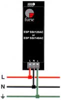
Install in parallel, within the trackside cabinet or equipment room. The protector should be installed on the load side of the fuses, at the secondary side of the step-down transformer. Connect, with very short leads, to phase (BX), neutral (NX or CNX) and earth. SSI supplies are generally under 100A, but if they exceed this level, the phase/live connecting leads should be fused.
|

Electrical Specification
| ESP SSI/M | |
| Maximum signal voltage' | 7V |
| Maximum common mode stand-off voltage | 90Vrms |
| Current rating | 100mA |
| In-line resistance | 4.5ohms |
| Leakage (Line to line impedance) (Line to earth impedance) |
1ohm |
| Differential Bandwidth (50ohm system) | 10MHz |
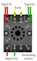
| ESP SSI/B |
| This is a modified 11 pin `relay type' socket containing a 10052 ±5% wire-wound 2.5W resistor connected between terminals 8 and 9. Internal links between terminals 2 & 3, 9 & 10, and 1 & 11. |
| ESP SSI/120AC | ESP SSI/140AC | |
| Nominal voltage (RMS) | 120V | 140V |
| Working voltage (RMS) | 90-150V | 90-165V |
| Frequency range | 40-60Hz | 40-60Hz |
| Current rating (supply) | Direct connection to supplies up to 100A. Connection via series fuses to supplies greater than 100A. See installation instructions. |
|
| Leakage current (to earth) | <60µA | <60µA |
| Indicator circuit current | <10mA | <10mA |
| Volt free Contact* - Current Rating - Nominal Voltage (RMS |
Screw Terminal 200mA 250V |
Screw Terminal 200mA 250V |
Transient Specification
| ESP SSI/M | |
| Transverse (Differential) `let-through' voltage' | 15V |
| Common mode `let-through' voltage' | 250V |
| ESP SSI/120AC | ESP SSI/140AC | |
| Let-through voltage (all conductors)' Let-through voltage (all conductors)' 6kV 1.2/50µs open circuit voltage, 3kA 8/20µs short circuit current to: BS 6651:1999 Appendix C, Cats C-Low & B-High IEEE C62.41-20022 Location Cats C1 & B3 AS 1768-1991 Appendix B, Cat B UL1449 mains wire-in |
400V | 500V |
Maximum surge current³ |
Mechanical Specification
| ESP SSI/M | ESP SSI/B | |
| Temperature Range | -25 to +70°C | -25 to+70°C |
| Connection Type | - | Screw Terminal |
| Fixing Connection - Flat Mount - Top Hat Din Rail Mount - G Din Rail Mount |
- | - Two M4 Fixing holes with 35mm centres |
| Max Load | - | 10A, 250V |
| Weight -unit -packaged per 50 |
0.065kg 3.25kg |
0.075kg 3.9kg |
| dimensions image |  |
|
| ESP SSI/120AC | ESP SSI/140AC | |
| Temperature range | -40 to +70°C | -40 to +70°C |
| Connection type | Screw terminal | Screw terminal |
| Conductor size | 16mm' | 16mm' |
| Earth connection | Screw terminal | Screw terminal |
| Volt free contact | Connect via screw terminal with conductor up to 2.5mm' (stranded) | |
| weight - unit - packaged |
0.5kg 0.6kg |
0.5kg 0.6kg |
| Dimensions image | 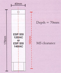 |
|