| |
|

|

|
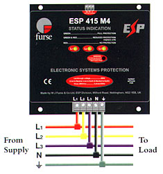
| Installation Install in parallel, within the power distribution board, either on the load side of the incoming isolator, or on the closest outgoing way to the incoming supply. Connect with very short connecting leads, to phase(s), neutral and earth. On supplies over 100 amps, phase/live connecting leads should be fused with a either a 63 or 100 amp high rupture capacity (HRC) fuses, a switchfuse, MCCB or type 'C' MCB. |
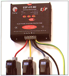
Parallel connection of ESP 415 M1 or ESP 208 M1 to three phase star (4 wire and earth) supplies. Where the protector can not be incorporated within the panel use the WBX M2 enclosure for the ESP 415 M2 or the WBX M4 for the ESP 415 M4.
|
| Electrical specification | ||||||||||||||||||||||||
|
||||||||||||||||||||||||
| Transient specification | ||||||||||||||||||||||||
|
| 1 The maximum transient voltage let-through the protector
throughout the test (+/-5%), phase to neutral, phase to earth and neutral
to earth. 2 Formerly IEEE 587 and ANSI C62.41. 3 Tested with 8/20Ás waveshape to BS 6651:1999 Appendix C. Note: The electrical system, external to the unit, may constrain the actual current rating achieved in a particular installation. |
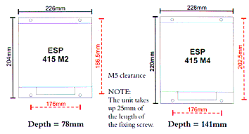
| Mechanical specification | ||||||||||||||||||||||||
|
||||||||||||||||||||||||
| |