| Home › Lightning & Surges Protection › Electronic Systems Protection |
|
| |
|
 |
|
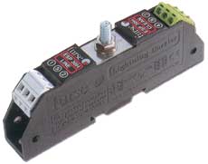
For some data and signal applications with lower current, higher in line resistance or higher bandwidth requirements, the D or E Series protectors may be more suitable. If the protector is to be mounted directly onto a PCB, use the ESP PCB/**D or ESP PCB/**E protectors. Application Use these applications to protect resistance sensitive or higher running current systems, eg systems with long signal lines, or DC power applications. Features and benefits |
|
||||||||||||||||||||||||||||||||||
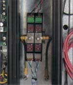
| Installation
Connect in series with the data communication or signal line either near where it enters or leaves the building or close to the equipment being protected (eg within the control panel). Either way, it must be very close to the system's earth star point. Install protectors either within an existing cabinet/cubicle or in a separate enclosure. |
Suitable accessories Simultaneously mount and earth up to 4 of these protectors on a CME 4, up to 8 on a CME 8, up to 16 on a CME 16 or up to 32on a CME 32. Enclosures suitable for up to two (WBX 2/G) or three (WBX 3/G) protectors, or a CME 8 and protectors (WBX 8) or one or two CME 16 kits and protectors (WBX 16/2/G).
|
| Electrical specification | ||||||||||||||||||||||||||||||
|
||||||||||||||||||||||||||||||
|
||||||||||||||||||||||||||||||
| Transient specification | ||||||||||||||||||||||||||||||
|
| 1 The maximum transient voltage let-through the
protector throughout the test (+/-10%), line to line and line to earth. Response time <10ns. |
| Mechanical specification | |||||||||||||||||||||||||||||||||||
|
|||||||||||||||||||||||||||||||||||