| |
|
|
Down conductors |
|
Down conductor positioning and distancing is often dictated by architectural constraints. There should be one down conductor for every 20m or part there of of the building perimeter at roof or ground level (whichever is greater).These should be evenly spaced and distances apart of more than 20m avoided if possible. If the building is above 20m in height or of an abnormal risk this distance should be reduced to 10m. They should be routed as directly as possible from the air termination network to the earth termination network to avoid risks of side flashing. Re-entrant loops are also to be avoided. BS 6651 recommends that the length of conductor forming the loop should not exceed eight times the width of its open side. BS 6651 allows the use of `natural conductors' such as rebars and structural
steelwork, provided that they are electrically continuous and adequately
earthed. | click image to enlarge |
| |

Earth termination networks Each
down conductor must have a separate earth termination. Moreover
provision should be made in each down conductor, for disconnection from
the earth for testing purposes.This is achieved with a test clamp (see
Figure 4). | ||
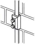 Figure 4 - Oblong test or junction clamp | BS 6651 stipulates that the resistance to earth of the lightning protection system measured at any point, should not exceed 10 ohms. With the test clamp disconnected, the resistance of each individual earth should be no more than ten times the number of down conductors in the complete system. eg for a system with 15 down conductors, the individual earth readings should be no more than 10 x 15 = 150 ohms. Several types of earth electrode are permissible, but by far the most commonly used are deep driven earth rods. BS 6651 states that the combined earth rod length of a system should be no less than 9m whilst each individual earth rod should be no less than 1.5m in length.
| 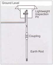 Figure 5 - Deep driven earth electrode |
| |