HomeLightning & Surges ProtectionElectronic Systems Protection

Electronic Systems Protection furse

ESP RF Protectors for Coaxial RF Systems

Suitable for RF systems using coaxial cables at frequencies between 50 MHz and 2.7GHz.
Effective protection without impairing system performance.
Suitable for power up to 150W.

For coaxial (or twisted pair) CCTV lines use the ESP CCTV models. For coaxial ethernet lines use the ESP Thin/ThickNet models and for CATV systems using the F connector the ESP CATV/F.

Application

Use on coaxial cables to protect RF transmitter and receiver systems, including electronics located at the antenna or dish. Typical examples include cell sites, military communications, satellite earth stations, pager systems and emergency services communications systems.

Features and benefits

Restricts let-through voltage to below the damage levels of interface circuitry.

Superior transient protection to both gas Discharge Tube (GDT) and Quarter Wave Stub (QWS) based protectors.

Provides repeated protection in lightning intense environments.

Low attenuation and near unity Voltage Standing Wave Ratio (VSWR) over a wide range of frequencies ensure the protectors do not impair system performance.

Wide bandwiidth means a single product is suitable for a range of applications.

Available with N, 7/16 DIN and BNC connectors.

Easily mounted and earthed via via fixtures on the base of the unit that accept M3 and M5 screws.

Additional mounting plates - ESP RF BK1 (straight) and ESP RF BK2 (90deg angled) - give increased flexibility in mounting methods.

Robust metal housing.

ESP RF installation
ESP RF 111A11 installed on a coaxial cable running between an antenna and an RF receiver.

ESP RF

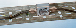
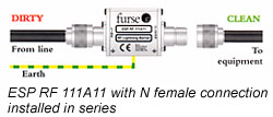
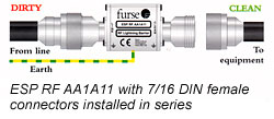
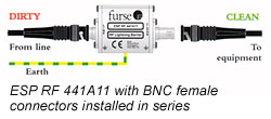
Installation

In a building, connect in series with the coaxial cable near where it enters or leaves the structure, or close to the equipment being protected. This should be close to the system's earth star point (to enable a good connection to earth). On a mast, connect in series with the coaxial cable near the antenna /dish being protected. Install in a radio communications room, an existing cabinet or suitable enclosure.

ESP RF 111A11


ESP RF AA1A11


ESP RF 441A11

Suitable Accessories

Additional mounting plates - ESP RF BK1 (straight) and ESP RF BK2 (90deg angled) - are available.

PDF

ESP RF Brochure

ESP RF DC Brochure

Electrical Specification


ESP RF 111A11
ESP RF AA1A11
ESP RF 441A11
Maximum working voltage (RMS)
86V
86V
86V
Characteristic impedance
50ohms
50ohms
50ohms
Bandwidth
50-2700MHz
50-2700MHz
50-2700MHz
Voltage standing wave ratio
<1.2
<1.2
<1.2
Insertion loss over bandwidth
0.2dB
<0.2dB
0.2dB
Maximum power
150W
150W
150W

Transient Specification


ESP RF 111A11

ESP RF AA1A11

ESP RF 441A11
Let-through voltage (all conductors)¹
5kV, 10/700µs test to:
BS 6651:1999 Appendix C, Cat C-High
ITU (formerly CCITT) IX K17
20V
20V
20V
Maximum surge current²
10kA
10kA
10kA
1 The maximum transient voltage let-through the protector throughout the test (+/-10%). Response time <10ns. This let-through voltage represents a deviation from the applied signal voltage , present at the time of the test.
2 Tested with 8/20µs waveshape to ITU (formely CCITT), BS 6651:1999 Appendix C.

Mechanical Specification


ESP RF 111A11
ESP RF AA1A11
ESP RF 441A11
Temperature range
-25°C to +70°C
-25°C to +70°C
-25°C to +70°C
Connection type
N female
7/16 DIN female
BNC female
Earth connection
Via mounting fixtures
Finish
Silver
Silver
Silver
Weight
-unit
-packaged
150g
180g
240g
270g
120g
150g

Dimensions

PDF

ESP RF Brochure

ESP RF DC Brochure